- 您现在的位置:买卖IC网 > Sheet目录505 > RXM-869-ES_ (Linx Technologies Inc)RECEIVER RF 869MHZ 16PIN SMD

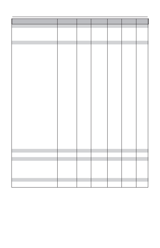
ELECTRICAL SPECIFICATIONS
Parameter
Designation
Min.
Typical
Max.
Units
Notes
POWER SUPPLY
Operating Voltage
Supply Current
Power-Down Current
V CC
I CC
I PDN
4.5
5.5
5.0
6.0
50.0
5.5
6.5
VDC
mA
μA
–
–
4
RECEIVER SECTION
Receive Frequency:
F C
RXM-869-ES
RXM-916-ES
–
–
869.85
916.48
–
–
MHz
MHz
–
–
Center Frequency Accuracy
–
-60
–
+60
kHz
–
LO Frequency:
F LO
RXM-869-ES
RXM-916-ES
–
–
859.15
905.78
–
–
MHz
MHz
–
–
IF Frequency
Spurious Emissions
Receiver Sensitivity
Noise Bandwidth
Audio Bandwidth
Audio Output Level
Data Rate
F IF
–
–
N 3dB
–
–
–
–
–
-92
–
20
–
200
10.7
-75
-97
280
–
360
–
–
-50
-102
–
28,000
–
56,000
MHz
dBm
dBm
kHz
Hz
mV P-P
bps
–
1
2
–
3,4
4,5
4
Data Output:
Logic Low
Logic High
V OL
V OH
–
V CC - 1.1
0.0
V CC - 1
0.1
V CC - 0.9
VDC
VDC
–
–
Power Down Input:
Logic Low
Logic High
V OL
V OH
0.0
2.8
–
–
0.8
V CC
VDC
VDC
–
–
RSSI:
Dynamic Range
Gain
Voltage with No Carrier
Voltage with Max Carrier
–
–
–
–
–
–
–
–
60
30
1.1
2.9
–
–
–
–
dB
mV/dB
V
V
4
4
4
4
ANTENNA PORT
RF Input Impedance
R IN
–
50
–
Ω
4
TIMING
Receiver Turn-On Time:
Via V CC
–
3.8
4.7
5.4
mSec
4,6
Via PDN
–
mSec
4,6
Max Time Between Transitions
–
–
5.0
–
mSec
4,7
ENVIRONMENTAL
Operating Temperature Range
–
0
–
+70
°C
4
Table 1: ES Series Receiver Specifications
Notes
1. Into a 50-ohm load.
2. For 10 -5 BER at 9,600 baud.
3. The audio bandwidth is wide to accommodate the needs of the data slicer. In audio applications, audio
quality may be improved by using a low-pass filter rolling off at the maximum frequency of interest.
4. Characterized, but not tested.
5. Input frequency deviation-dependent.
6. Time to receiver readiness from the application of power to V CC or PDN going high.
7. Maximum time without a data transition.
Page 2
发布紧急采购,3分钟左右您将得到回复。
相关PDF资料
RXM-GPS-SG-T
GPS MODULE SMD SIRF
RXM-GPS-SR-T
GPS MODULE SMD SIRF W/ANT
RZE002P02TL
MOSFET P-CH 20V 200MA EMT3
RZF020P01TL
MOSFET P-CH 12V 2A TUMT3
RZF030P01TL
MOSFET P-CH 12V 3A TUMT3
RZM002P02T2L
MOSFET P-CH 20V 0.2A UMT6
RZQ045P01TR
MOSFET P-CH 12V 4.5A TSMT6
RZQ050P01TR
MOSFET P-CH 12V 5A TSMT6
相关代理商/技术参数
RXM-900-HP3
制造商:未知厂家 制造商全称:未知厂家 功能描述:HP3 SERIES RECEIVER MODULE DATA
RXM-900-HP3-PPO
功能描述:射频模块 RF Receiver 900MHz 8-CH SIP Pack
RoHS:否 制造商:Linx Technologies 产品:Transceiver Modules 频带:902 MHz to 928 MHz 输出功率:- 15.5 dBm to + 12.5 dBm 接口类型:UART 工作电源电压:- 0.3 VDC to + 5.5 VDC 传输供电电流:38.1 mA 接收供电电流:22.7 mA 天线连接器类型:U.FL 最大工作温度:+ 85 C 尺寸:1.15 mm x 0.63 mm x 0.131 mm
RXM-900-HP3-PPO_
功能描述:RECEIVER RF 900MHZ 8-CHANNEL RoHS:是 类别:RF/IF 和 RFID >> RF 接收器 系列:HP3 产品培训模块:Lead (SnPb) Finish for COTS 产品变化通告:Product Discontinuation 09/Jan/2012 标准包装:50 系列:* 频率:850MHz ~ 2.175GHz 灵敏度:- 数据传输率 - 最大:- 调制或协议:- 应用:* 电流 - 接收:* 数据接口:PCB,表面贴装 存储容量:- 天线连接器:PCB,表面贴装 特点:- 电源电压:4.75 V ~ 5.25 V 工作温度:0°C ~ 85°C 封装/外壳:40-WFQFN 裸露焊盘 供应商设备封装:40-TQFN-EP(6x6) 包装:托盘
RXM-900-HP3-PPS
功能描述:射频模块 RF Receiver 900MHz 8 & 100-CH SIP Pack RoHS:否 制造商:Linx Technologies 产品:Transceiver Modules 频带:902 MHz to 928 MHz 输出功率:- 15.5 dBm to + 12.5 dBm 接口类型:UART 工作电源电压:- 0.3 VDC to + 5.5 VDC 传输供电电流:38.1 mA 接收供电电流:22.7 mA 天线连接器类型:U.FL 最大工作温度:+ 85 C 尺寸:1.15 mm x 0.63 mm x 0.131 mm
RXM-900-HP3-PPS_
功能描述:RECEIVER RF 900MHZ 8PAR/120SRLCH RoHS:是 类别:RF/IF 和 RFID >> RF 接收器 系列:HP3 产品培训模块:Lead (SnPb) Finish for COTS 产品变化通告:Product Discontinuation 09/Jan/2012 标准包装:50 系列:* 频率:850MHz ~ 2.175GHz 灵敏度:- 数据传输率 - 最大:- 调制或协议:- 应用:* 电流 - 接收:* 数据接口:PCB,表面贴装 存储容量:- 天线连接器:PCB,表面贴装 特点:- 电源电压:4.75 V ~ 5.25 V 工作温度:0°C ~ 85°C 封装/外壳:40-WFQFN 裸露焊盘 供应商设备封装:40-TQFN-EP(6x6) 包装:托盘
RXM-900-HP3-SPO
功能描述:射频模块 RF Receiver 900MHz 8-CH SMD Pack
RoHS:否 制造商:Linx Technologies 产品:Transceiver Modules 频带:902 MHz to 928 MHz 输出功率:- 15.5 dBm to + 12.5 dBm 接口类型:UART 工作电源电压:- 0.3 VDC to + 5.5 VDC 传输供电电流:38.1 mA 接收供电电流:22.7 mA 天线连接器类型:U.FL 最大工作温度:+ 85 C 尺寸:1.15 mm x 0.63 mm x 0.131 mm
RXM-900-HP3-SPO_
功能描述:RECEIVER RF 900MHZ 8-CH SMD RoHS:是 类别:RF/IF 和 RFID >> RF 接收器 系列:- 产品培训模块:Lead (SnPb) Finish for COTS 产品变化通告:Product Discontinuation 09/Jan/2012 标准包装:50 系列:* 频率:850MHz ~ 2.175GHz 灵敏度:- 数据传输率 - 最大:- 调制或协议:- 应用:* 电流 - 接收:* 数据接口:PCB,表面贴装 存储容量:- 天线连接器:PCB,表面贴装 特点:- 电源电压:4.75 V ~ 5.25 V 工作温度:0°C ~ 85°C 封装/外壳:40-WFQFN 裸露焊盘 供应商设备封装:40-TQFN-EP(6x6) 包装:托盘
RXM-900-HP3-SPS
功能描述:射频模块 RF Receiver 900MHz 8 & 100-CH SMD Pack
RoHS:否 制造商:Linx Technologies 产品:Transceiver Modules 频带:902 MHz to 928 MHz 输出功率:- 15.5 dBm to + 12.5 dBm 接口类型:UART 工作电源电压:- 0.3 VDC to + 5.5 VDC 传输供电电流:38.1 mA 接收供电电流:22.7 mA 天线连接器类型:U.FL 最大工作温度:+ 85 C 尺寸:1.15 mm x 0.63 mm x 0.131 mm
